MOIRE Structural Analysis

Introduction
NOTE: All the information I share here is public knowledge and readily available in published papers and public media. I always seek to protect intellectual property.
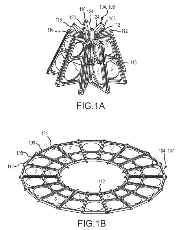
The Membrane Optical Imager Real-time Exploitation (MOIRE) program was sponsored by the Defense Advanced Research Projects Agency (DARPA). The picture at the top of this page shows what DARPA envisioned the system might look like. Their goal was a 100-meter long system with a 20-meter wide aperture. The whole thing bundled and folded on itself to fit inside a single rocket fairing, then it deployed and operated with over 200 mechanisms. It was to be a giant diffractive telescope using a pattern etched into a “zero CTE” membrane.
You can watch a short video of how it deployed and what the production system would resemble:
My role was to lead the structures and mechanisms analysis. This was a multi-year job that spawned three presented papers, a patent, travel to vendors, and a suite of custom Matlab code to help me dig deep into Monte Carlo approaches. A big part of my work estimated impacts on the membrane optics from jitter, temperature deltas, humidity changes between earth and orbit, and bounding variations in manufacturing. Work also included typical structural analysis tasks such as launch loads, optic flexure optimization, composite sizing, and fastener selection. I often delegated these things to analysts supporting me. I primarily used NASTRAN and LS-DYNA as the finite element solvers.
Membrane Analysis
The telescope's key technology was membrane optics that diffracted (rather than reflected) light at the aperture onto correcting optics at the base of the telescope. Their lightweight nature enabled the 20-meter diameter aperture as well as relaxation of some things such as out-of-plane alignment that refractive telescopes can struggle with. Of course, new challenges are introduced with membranes that glass rarely deals with, such as in-plan deformation and being torn apart from acoustic loading.
Membrane Uniformity Study
The membrane material was manufactured by NeXolve Corporation then sent to Lawrence Livermore National Laboratory for etching. The etching process worked similar to methods used to make microchips. The membrane was theoretically a “zero CTE” material, meaning that it would not change dimensions due to temperature variations. However, my team’s analysis and testing of samples showed that small differences in local thickness and chemical mixtures led to small “non-zero CTE” realities that varied across the span of the large optic surfaces. How could we model these variations and determine their impact on the optic performance? And, if the deformations exceeded thresholds, could we design a metrology system to compensate for the errors?
I decided on a Monte Carlo approach. Each iteration did the following:
- Start with a large mesh using CQUAD4 elements of equal area
- Randomly pick points on the mesh and apply random values of material properties from distribution curves determined from testing
- Use Gaussian smoothing techniques from image processing algorithms to create distributions across the mesh.
- Repeat steps 2 and 3 for all the material properties such as thickness and elastic modulus
- “Cut out” the membrane shape from the material. Tested shapes include squares, ovals, and trapezoids.
- Apply boundary condition smoothing and modeling for square elements converted to triangles.
- Add the frame model to the membrane mesh
- Run analysis for various environmental loads
- Pull data from output files and process in follow-on models
- Repeat the above until an understanding of the distribution of potential outcomes was reached
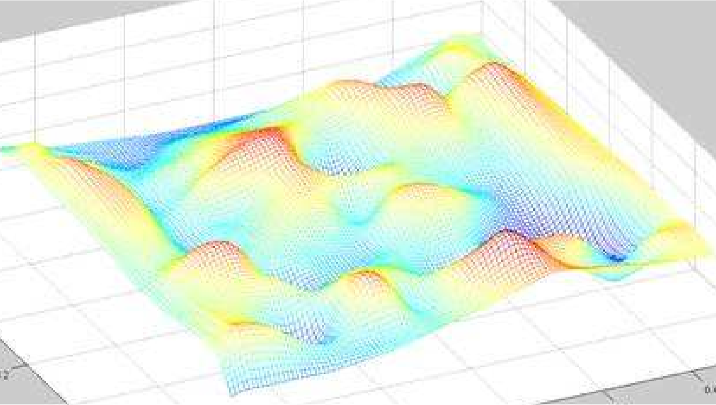
The image below shows an example distribution of membrane material properties. Peaks are higher values of thermal expansion coefficients and valleys are lower values.
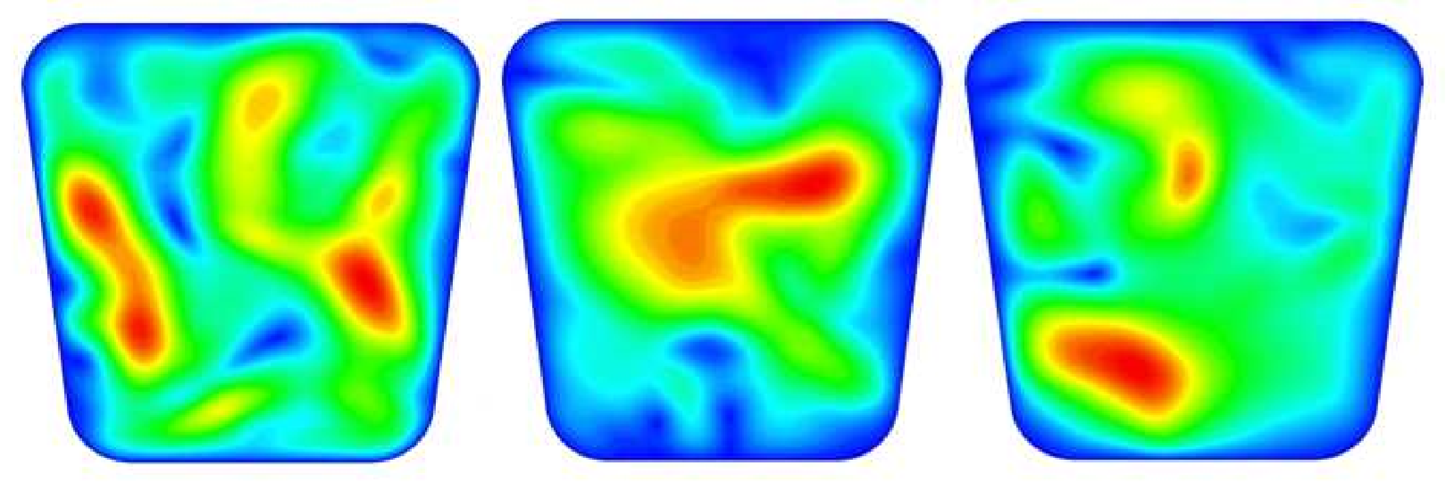
The next image shows membrane displacement results. Red means higher in-plane displacements, blue means lower displacements. Data sets such as these fed downstream models, including a wavefront error model I built. Those results, in turn, set limits on manufacturing variations and/or environmental loads.
Frame Loads
The membrane was shipped to Ball in a tensioned hoop. Then Ball applied a production frame to it and cut the material out from the hoop. The questions were:
- What tension should the hoop apply to the membrane to prevent wrinkles, but not stretch the material?
- How do we apply the membrane’s starting tension to the frame’s boundary condition so that subsequent stress field analyses were accurate?
I answered the first question by directing numerous material tests studying material fatigue, creep, and elasticity curves. I combined those distributions with straightforward modeling to determine a safe hoop stress.
To answer the second question, a membrane model with the frame’s outline embedded at proposed bonding locations was created. The membrane’s internal loads from the hoop were simulated with thermal loading. I imported nodal force balances (used to prove the sum of forces is zero) into Matlab and extracted reacting forces at the frame’s boundary nodes. These values were converted to node force boundary conditions on a model of the frame and written in NASTRAN format to a file. The final model was run to determine frame deformations, which fed the downstream models such as my wavefront error model. The process allowed for varying hoop loads, frame placements, and frame designs, including non-uniformity conditions within the membrane.
This image is an example of a wavefront error analysis result for a circular membrane in a bolted frame. (One of the trade studies was investigating bonded vs. bolted frames.)

Acoustic Loading
A major concern for large membrane surfaces is acoustic damage during launch. However, ground handling is also of interest since air turbulence can cause drumhead like motion of the membrane, which raises concern about material durability over time. In other words, we needed to understand the risk of catastrophic failure as well as micro-yielding. This was challenging work because the material has highly non-linear stiffness properties, which makes traditional acoustic analysis unusable. (Most acoustic analyses rely on a FE package to solve for the stiffness matrix, which is then used to apply increasing static pressure levels in a linear solution.)
However, because the stiffness matrix of a membrane changes as a function of pressure levels, it was necessary to solve for a new stiffness matrix at each pressure level step. Yet this was still inadequate because the launch environment does not step up in even pressure levels; launch events create random blasts of acoustic energy.
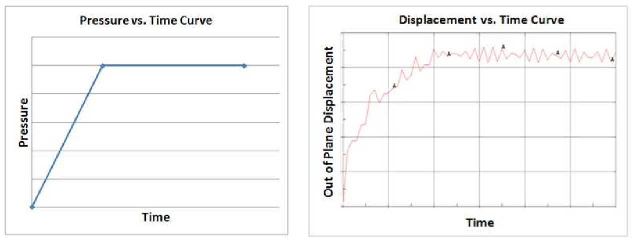
I investigated the problems primarily using LS-DYNA and NASTRAN’s non-linear, time-domain solver. An example result from this work is in the image below, where a pressure vs. time curve was input into the solver with a meshed frame and membrane. The resulting displacement shows the membrane billowing in and out of the frame. Follow-on work included creating random acoustic inputs similar to a random vibration input. Stress results recovered from these analyses were used to drive acoustic panels to dampen loads to acceptable levels.
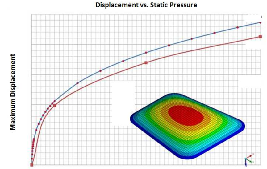
It was also important to understand the variations in solvers. The image below compares NASTRAN with LS-DYNA using the same mesh and inputs. Agreement was sufficiently close to trust LS-DYNA, which has a more stable non-linear solver.
System Studies
The membrane optics received significant attention because of their unique non-linear properties. The 100-meter structure was, of course, also novel with more than 200 mechanisms including deployable booms, moving mirrors, and a massive sunshade that behaved like a solar sail.
Modes
Modal analysis was straightforward. Both beam models and detailed meshes were used with both approaches yielding similar results. As expected, a 100-meter structure features dominant modes well below 10 Hz. The deployable booms drove the bulk of the frequencies below 100 Hz.
Control Studies
A primary purpose of modal studies is to develop control system requirements. An on-board metrology system monitored optic performance in real-time to correct optics with a set of actuators. Understanding how the system performed with thermal and vibration led to transfer function plots that determined the refresh rate of the control loop.
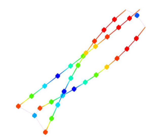
The image below shows example results due to translational and rotational inputs at the base of the telescope.

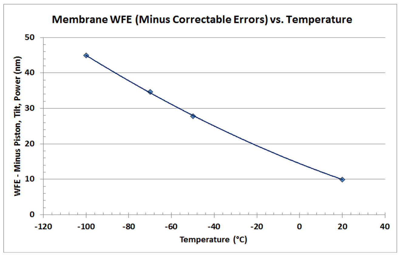
The next image shows the remaining wavefront error in the system after removing the piston, tilt, and power Zernike terms from a thermal analysis that included the membrane and frame.
Sunshade and Thermal Scenarios
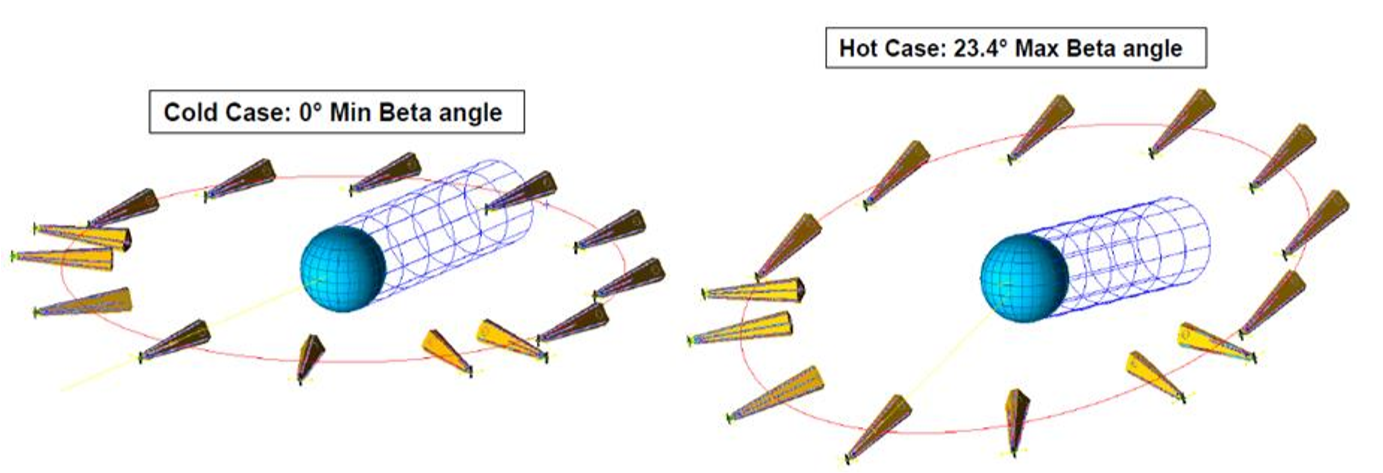
MOIRE was designed to operate in a geosynchronous orbit. Among other challenges, this created variances due to seasonal variation in Beta angles. The image below demonstrates the extremes.
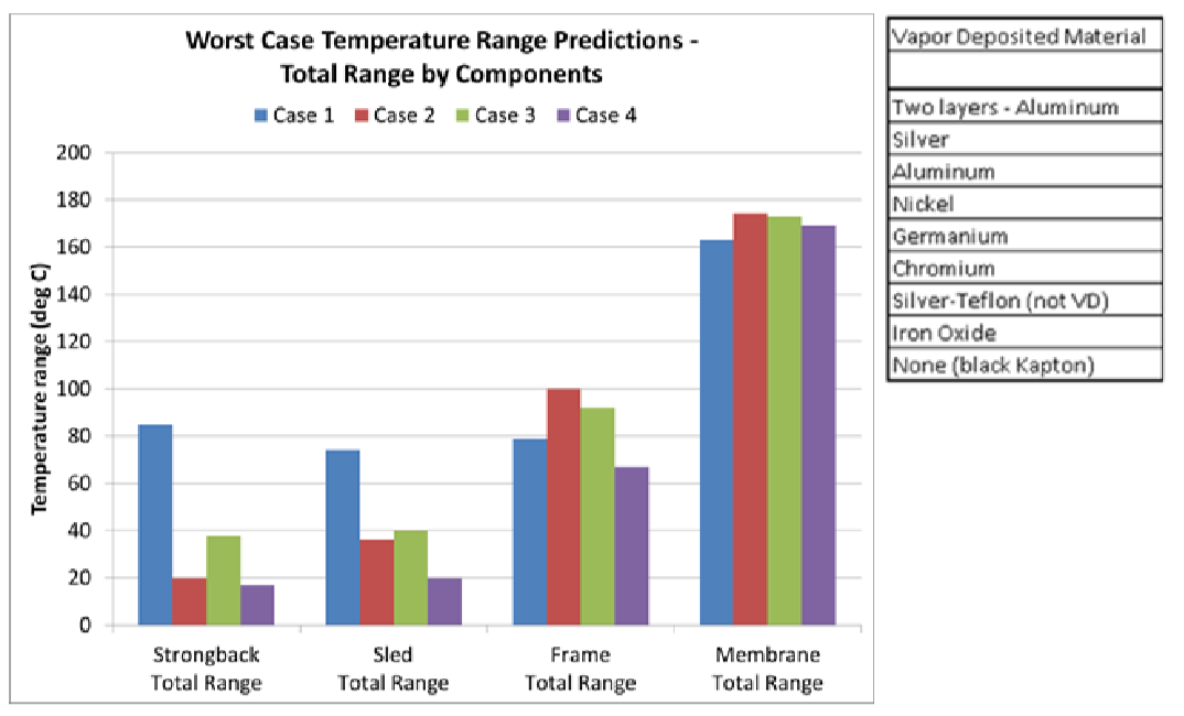
One of the questions raised by these variances is, “What sunshade materials reduce the seasonal temperature variations at various points in the system?”. I worked with a thermal engineer on this analysis by providing models that he applied a thermal mesh to. Then he returned mapped temperatures to me for further analysis. The image below shows four sunshade material cases as well as a list of other cases. Unfortunately, I’m not able to share what materials the cases represent.
Ground Support Equipment
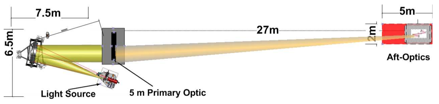
Ground testing was a big part of the contract. Testing was based on a “small” version of the telescope, although you can see in the image below that this required significant real estate.
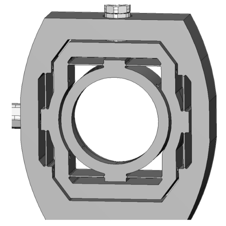
My role included responsibility for analysis of all the ground support equipment including frames, lifts, tables, mounts, and mechanisms. Many of the optic mounts required optimization to provide sufficient stiffness while remaining controllable with various types of precision actuators. Analysis actuated optics in a gravity field and through temperature extremes, then recovered displacements, stresses, and wavefront error. The image below shows an example optic mount, where the circular knobs are locations for actuator interfaces.
Papers and Patents
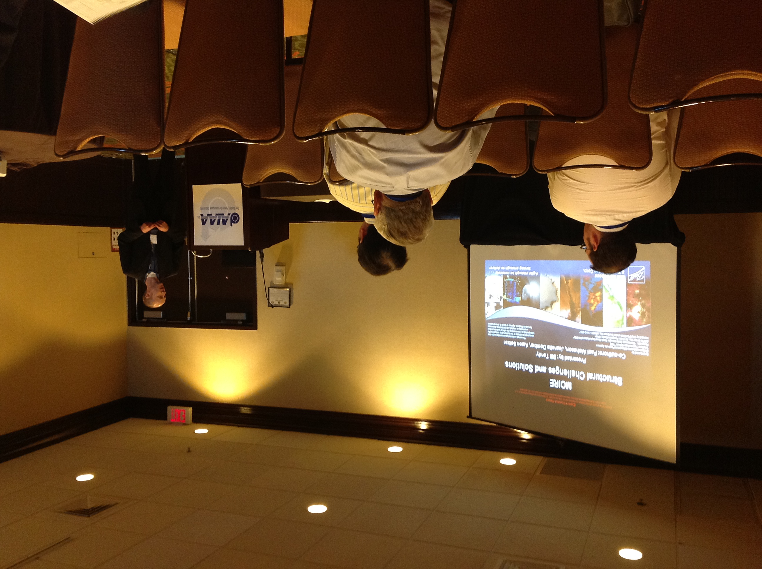
I wrote a series of three papers for the AIAA structures conferences. Here's me presenting one of them to what became a standing room only crowd.
And here are the three papers:
The patent covered the deployment method for the aperture. We went through many variations and studies before settling on this approach. The final system was tested with a novel "zero G" rig. A PDF of the patent can be found here: Patent PDF
Final Thoughts
The contract with DARPA ended without a flight mission. However, the program continues on in spirit with different entities seeking to build on what we established. Goddard is rumored to be working on a version, for example.
For myself, I’ve worked a lot of fun projects that pushed the envelope, but this was definitely the biggest! MOIRE was a significant effort requiring creative thinking, custom tools, and a mindset of organization and I’m proud to have been a part of it.